[UPDATE: Also check out my May 2023 post "Chasing weather satellites: the sequel" for further satellite adventures.]
No matter where you are on Earth, several weather satellites pass overhead at least twice a day, broadcasting real-time imagery of what they see below. The most well-known of these satellites, at least in amateur radio circles, are the American NOAA and Russian Meteor satellites.
The NOAA satellites (there are currently three of them, NOAA-15, -18, and -19) broadcast at around 137 MHz in the analog Automatic Picture Transmission (APT) format. (They also broadcast digital formats at a much higher frequency, but that requires a high-gain antenna with a way to track the satellite as it passes over, significantly complicating the task.) The Russian Meteor-M 2 satellite also broadcasts around 137 MHz, but in the digital low-rate picture transmission (LRPT) format. By way of comparison, digital LRPT has a resolution of 1 km/pixel, while analog APT is 4km/pixel.
In the not-too-distant past, you needed dedicated, expensive hardware to receive these transmissions. But with software-defined radio (SDR), the entry barriers to obtaining real-time weather satellite imagery are much lower. You can get a basic SDR dongle for $10, and construct a simple antenna for even less.
As I mentioned in a previous post, I've been a fan of SDR for some time. I've picked up pager and GSM traffic, ADS-B transmissions from aircraft, devices in the ISM band, and more. Getting imagery from weather satellites had been on my "to-do" list for some time, and it just so happened that I now had a high, partially flat roof with a mostly unobstructed view of the horizon, except for some trees to the north.
Bird is the word
First though, I needed an antenna suitable for receiving satellite transmissions. The popular V-dipole is easy to make, and looked like a good proof-of-concept. Before I built one though, I fished out an old TV "rabbit ears" antenna I had laying around, and as specified in the V-dipole plans, bent the elements to a 120 degree angle and extended them out to 54 cm to receive at 137 MHz.
I used the Look4Sat app to determine when a satellite would pass over my location. I hooked up the antenna to the SDR dongle, and listened in using the SDR receiver software Gqrx.
Despite hanging the antenna out on a window ledge, which was not ideal (you want the antenna up higher with a clear view of the sky) I was able to hear faint beeps of the NOAA "bird" as it went over. The signal was not nearly strong enough to get any imagery or useful data, but it was something, and all the encouragement I needed to press ahead.
The V-dipole antenna
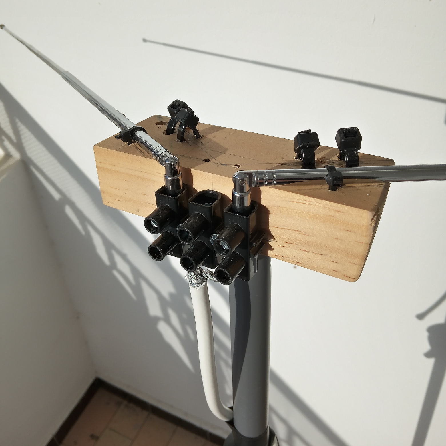
I set about building a dedicated V-dipole antenna. Again, construction of this antenna is simple. I took two telescoping antennas (purchased from AliExpress) and mounted them on a block of wood with 120 degrees of separation. Then I took an RG-6 coax cable, ran the core to one of the antennas, and the shield to the other, using a terminal block to connect everything. I mounted the entire contraption on a pole (in this case a mop handle), extended the elements out to 54 cm, and it was ready to go:
I went up on the roof, and after some trial and error with Gqrx settings, I received my first usable transmission. I ran the wav file through an APT decoder, and got my first, grainy image:
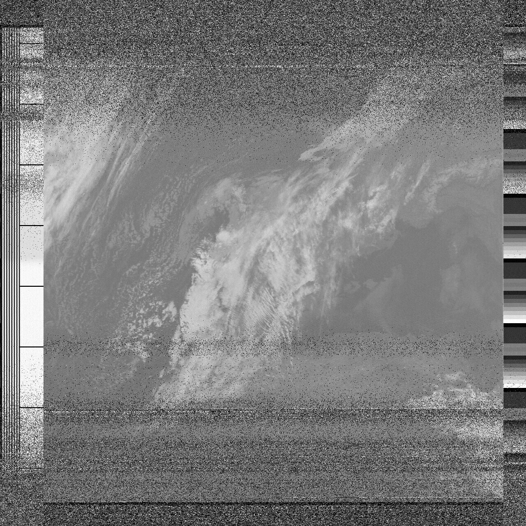
Okay, there was a lot of noise, and it was hard to pick out landmasses (this was a night pass), but there were definitely clouds visible there. Over the next several days, I caught more passes, with varying levels of success. With the V-dipole I could get some imagery, but there were significant limitations. There were "nulls" or dead zones where the signal dropped out. And the antenna needed fairly high elevation passes to get usable imagery. (Passes are measured in degrees, with 0 degrees at the horizon, and 90 degrees directly overhead. The quality and type of antenna, among other factors, helps determine the minimum pass elevation that yields useful data.)
The V-dipole was a good first antenna for experimenting, but I would have to build something else to get higher-quality images.
Enter the turnstile
There were several possibilities for satellite antennas, but the quadrifilar helix (QFH) and turnstile appeared to be the most popular. The turnstile looked easier to construct given the limited materials I had at hand, so I decided to go with that.
There are several plans online for turnstile antennas, but I chose this one from an Italian amateur radio enthusiast (see page 8 of the PDF).
I didn't want to just build the antenna blindly though -- I wanted to have an idea of where the lengths for the dipoles, cables, and so on came from. I'm no RF engineer, so I went down the rabbit hole a bit to get the answers, but it was a good learning experience.
Details: Click here for a side discussion into physics and measurements
In the schematic, the total dipole length is 109 cm, with each element 54 cm. (Note that this matches the 54 cm used in the V-dipole antenna.) The speed of light in a vacuum is around 300,000 km/second, or 300,000,000 meters/second. The weather satellites broadcast from around 137.1 MHz to 137.9 MHz, so we choose the middle value of 137.5 MHz, or 137,500,000 Hz (cycles per second). To get the wavelength for 137.5 MHz, we divide the speed of light by the frequency. In other words, dropping the extra zeros, 3000 divided by 1375, which gives us a 2.18 meter wavelength. For a half-wavelength dipole, divide 2.18 by 2, which equals 1.09 meters, or 109 cm. A 1 cm gap between the two elements of the dipole leaves us with two 54 cm segments as specified in the plans. Why a half-wavelength dipole, you may ask? It all comes down to "catching the wave" and here I defer to Wikipedia, which has some nice animations.
Moving on to the reflector elements, I read in several places that the reflectors should be around 5% longer than the driven dipoles. (I have yet to see an explanation for why 5% is the magic number, however.) In any event, taking the dipole length of 109 cm and adding 5% we get 114.45 cm, or the 114 cm shown in the schematic. So far, so good. As for the distance between the dipoles on top and the reflectors below, some sources said "a little less than a quarter-wavelength distance." Again, I have yet to see a formula or explanation for this. But the 46 cm specified is indeed "a little less" (about 15% less) than a quarter-wavelength, so I would just have to go on faith there.
With the dipole and reflector calculations mostly demystified, there was the matter of phase and polarization. A weather satellite's orientation in space is constantly changing through rotation, so it uses a circularly polarized signal to counteract this. To get a circularly polarized antenna, the coax core and shield must connect to specific dipole elements, and the two dipoles must be out of phase with each other by 90 degrees (or a quarter-wavelength, as 90/360 = 1/4). In theory, this means that the coax to one of the dipoles should be 1/4-wavelength longer than the coax to the other dipole. In practice, though, RF energy travels slower in coax cable than in a vacuum, and this value is expressed as the velocity factor. The RG-58 cable I was using had a velocity factor of 0.66. So 1/4-wavelength, or 54 cm, multiplied by 0.66 gives us 35.64 cm, which is close to the difference between the 35 cm and 72 cm cable sections shown in the schematic.
The final bit was the matching section of 75 ohm coax to get the impedance to around 50 ohms. Mismatched impedances means less signal reaching the receiver, which we obviously do not want. The quarter-wavelength coax matching section appears to be the most commonly used technique to match impedances. The 75 ohm RG-59 cable I was using had a velocity factor of 0.78, so 54 cm multiplied by 0.78 gives us 42 cm, which is close to the 43 cm shown in the schematic. So that checked out as well.
Still with me? Let's return to the main tale...
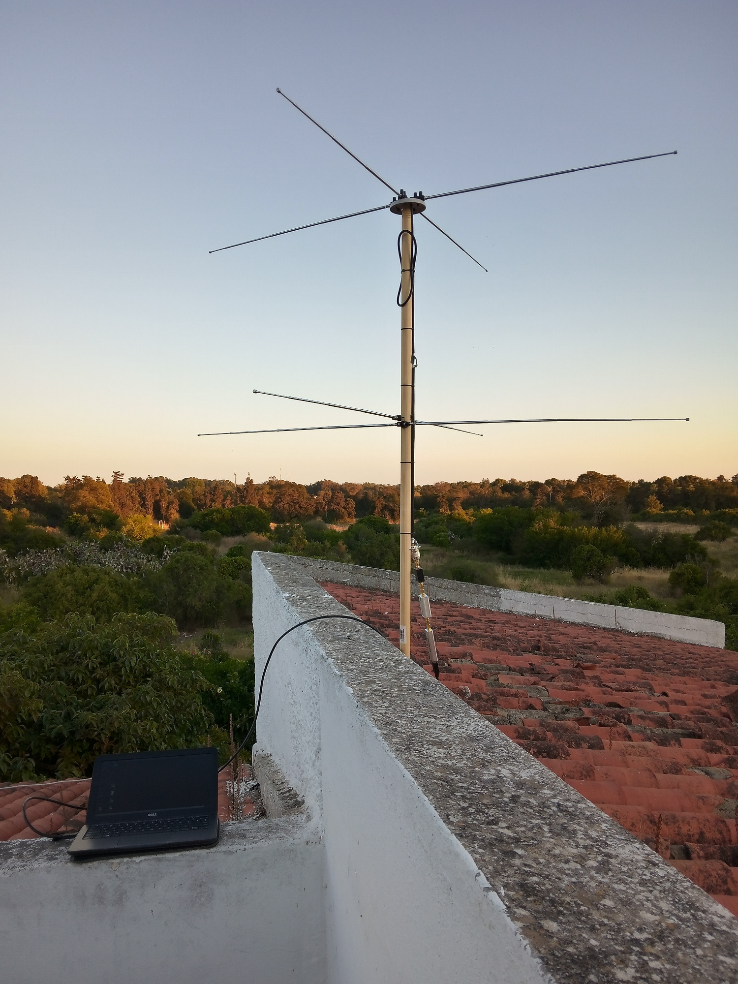
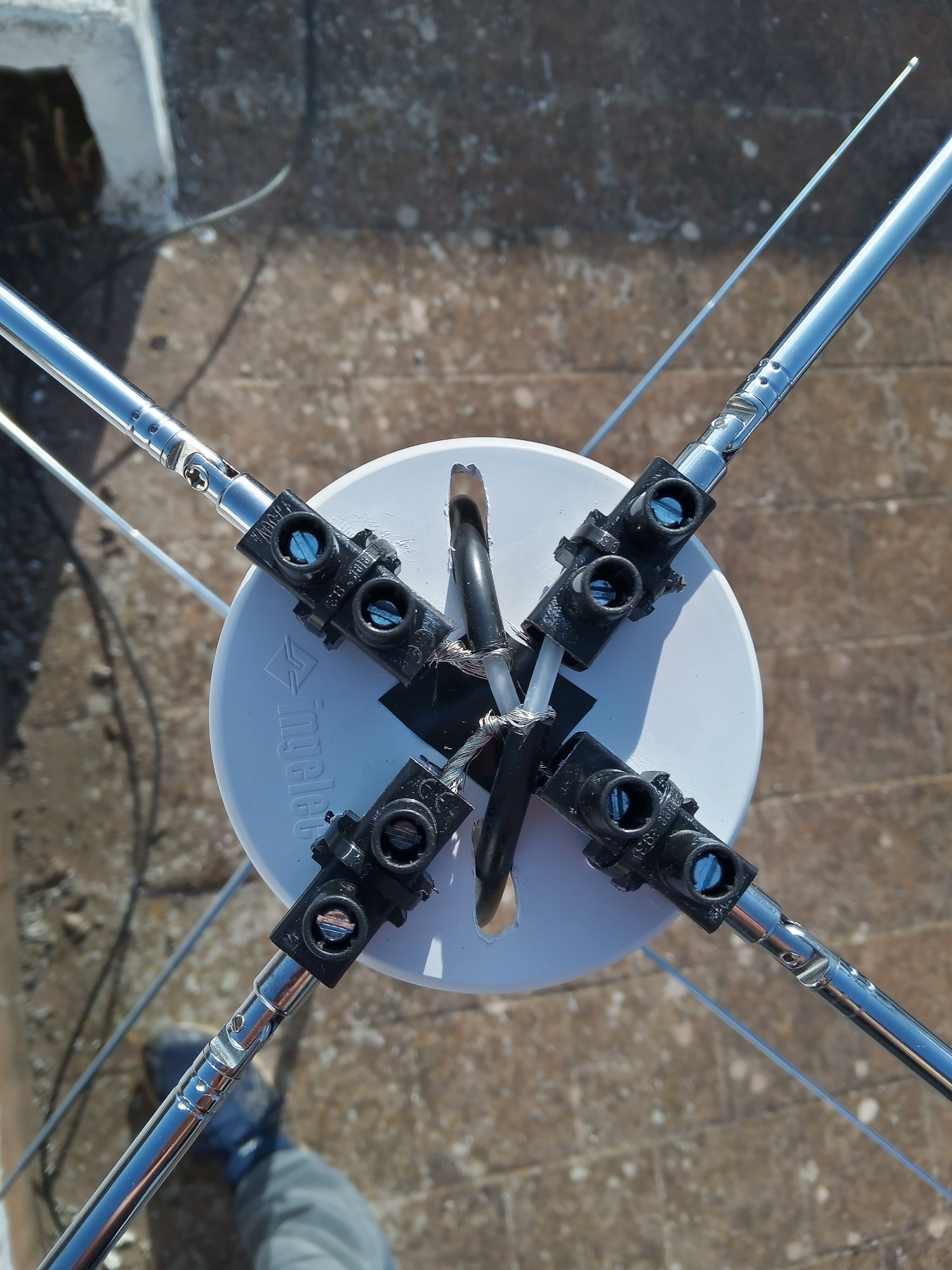
I used a bunch of telescopic antennas (eight total) for the dipoles and reflectors. Terminal blocks came in handy again for connecting everything up. With a wooden broom handle to support everything, I had my first prototype turnstile antenna. I went up on the roof and set everything up:
As the satellite came over the horizon, faint lines appeared in the spectrum waterfall in Gqrx. The signal faded in and out below about 20 degrees, which was expected -- a turnstile designed for satellite reception has a radiation pattern that is weak towards the horizon, and stronger overhead. (The national broadcaster's huge FM transmitters about 2 miles directly to the south of my location may have interfered as well.) By about 25 degrees elevation, a decent signal was coming through. When you hear the 'tick-tock' in between the high-pitched tones, you know you're getting a good, strong signal. Here's an audio clip from one of my captures:
Audio sample from NOAA satellite
The signal maintained its strength as the bird went overhead, with virtually no interference or noise. This was in contrast to the V-dipole, which would sometimes drop out when a satellite was high overhead.
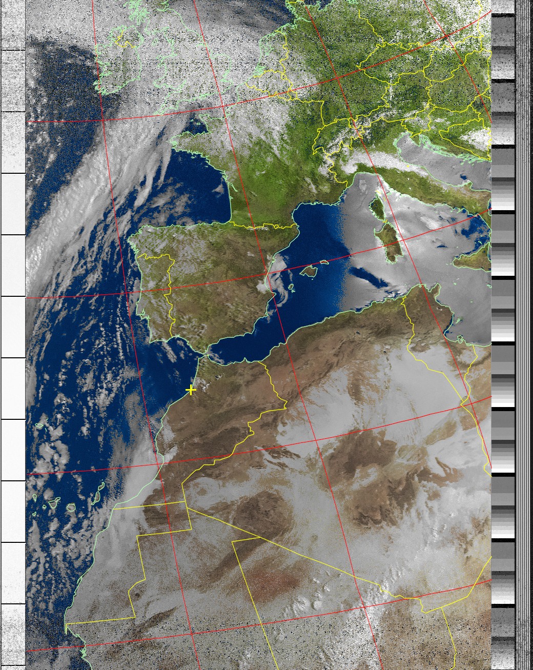
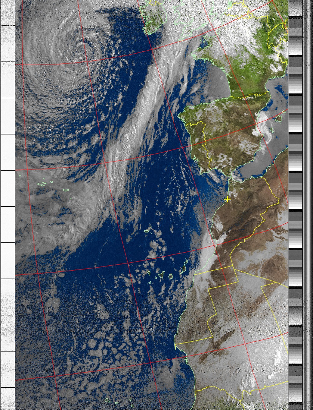
I caught some more passes, adding an LNA (low-noise amplifier) into the mix to boost the signal. After processing the captured signals with the excellent WXtoImg program I had some nice images from the NOAA birds:
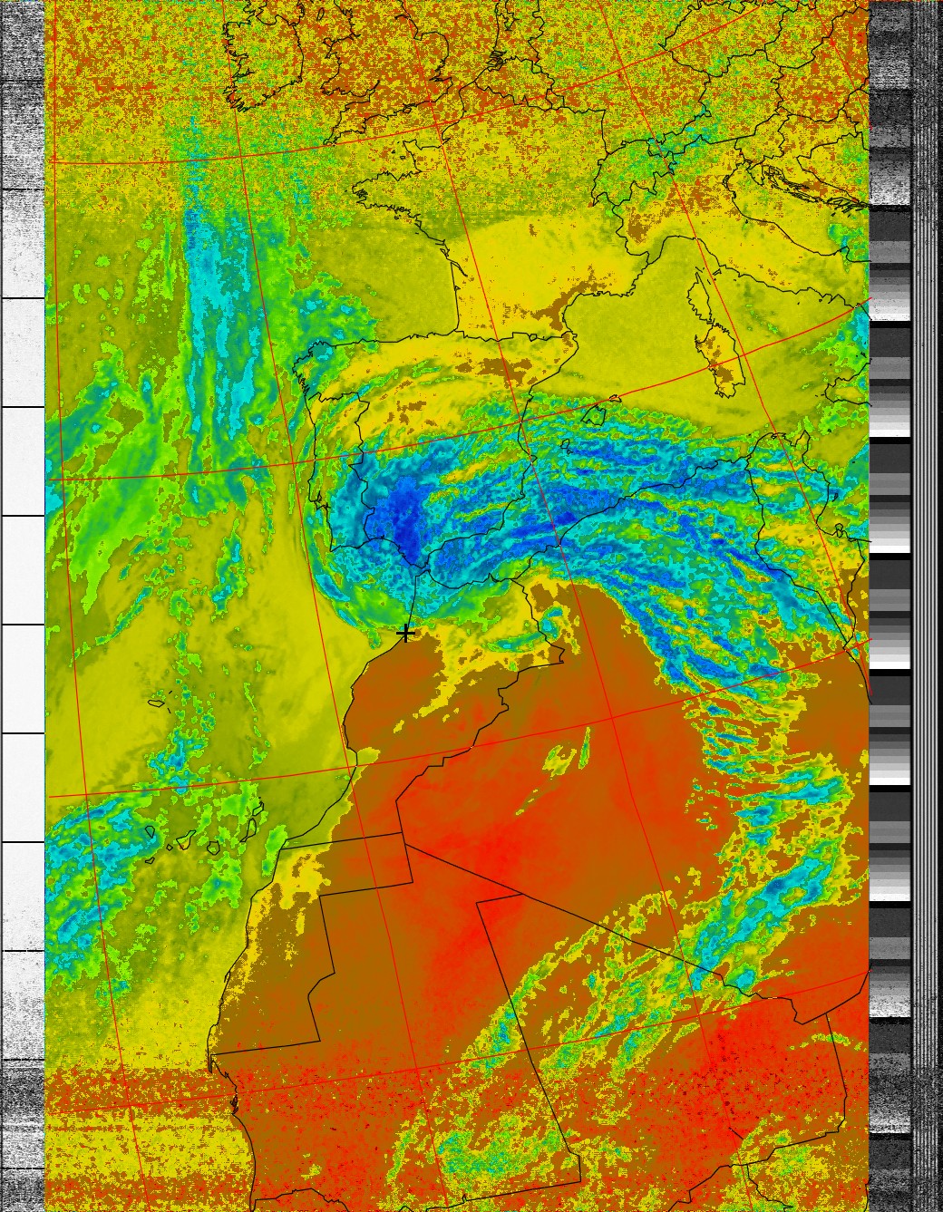
WXtoImg has numerous imagery enhancements to choose from -- this is a pass with the thermal filter applied:
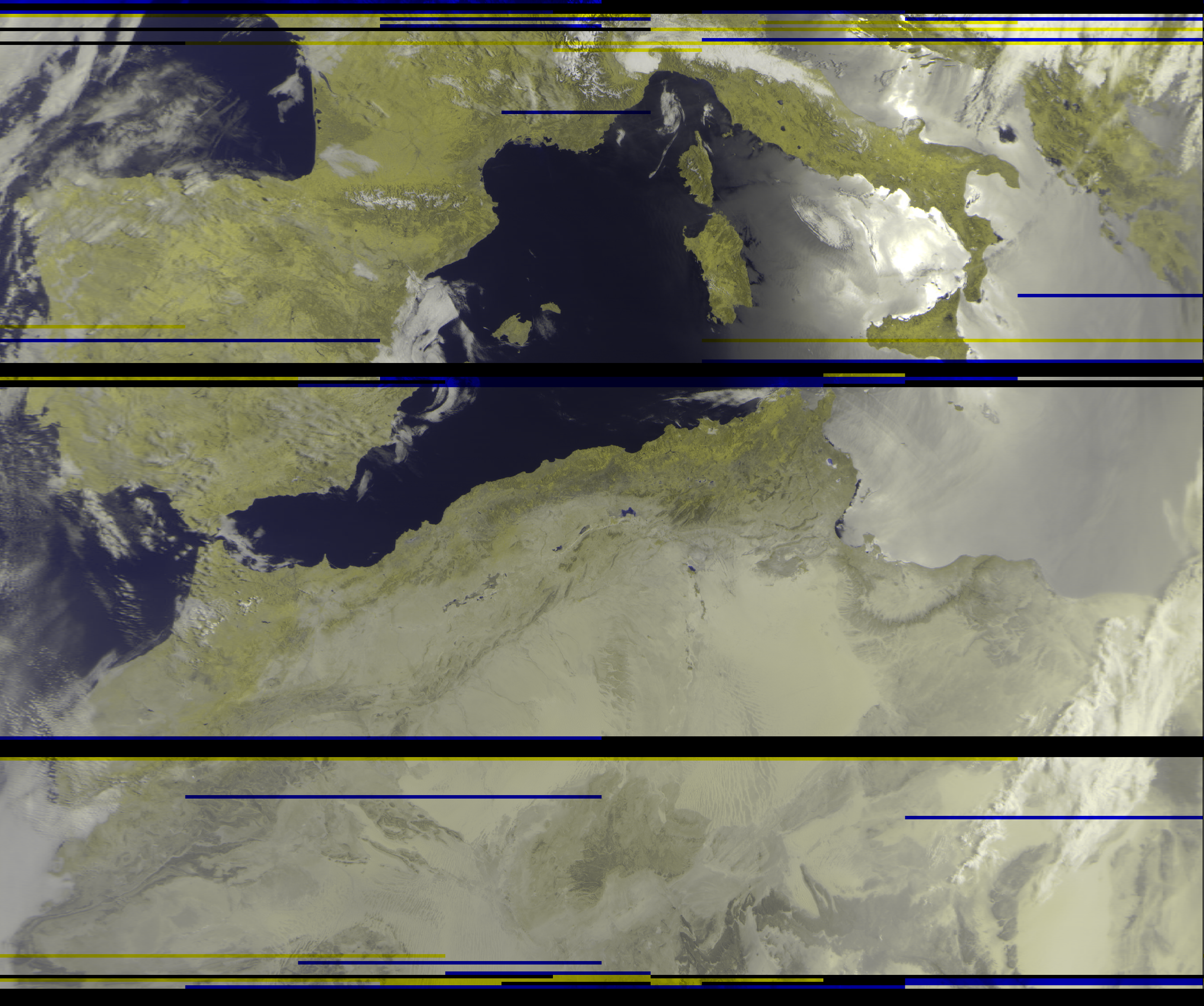
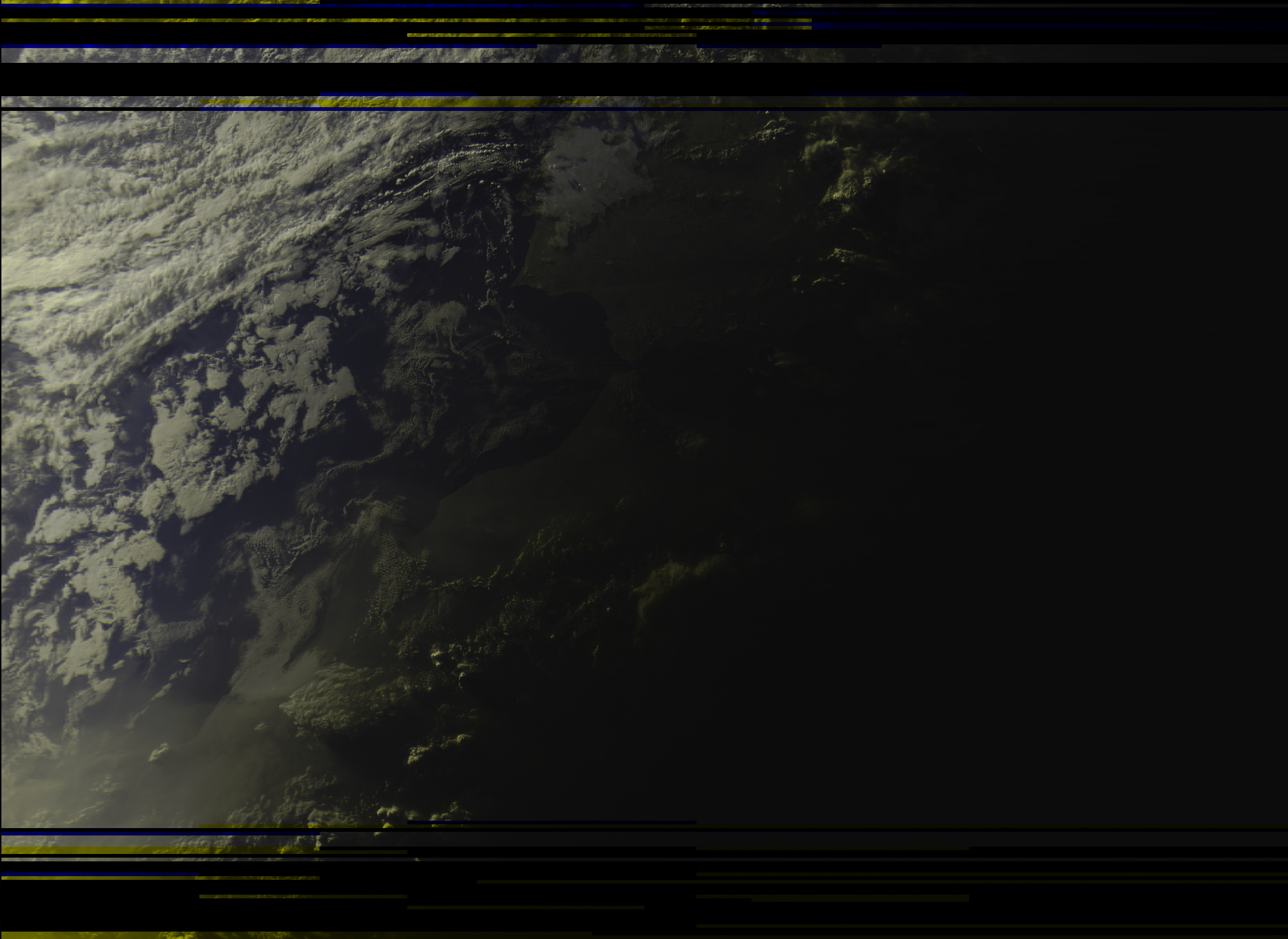
As I mentioned above, the Russian Meteor satellite transmits a digital signal, so it is less forgiving. Any interference or dropouts results in lost data and stark lines in the image. Still, the much higher resolution as compared to the NOAA APT imagery makes up for it:
Next steps
I'm pleased with the turnstile's performance, especially as I'm flying blind with regards to its RF characteristics, such as frequency resonance, phase, and SWR (standing wave ratio, a measurement of impedance mismatches). I think the next step is to get a vector network analyzer (VNA) like this one to measure how closely the antenna's real-world performance matches the theoretical calculations.
Another priority is to weather-proof the antenna and run a cable to inside the house. Then I can chase satellites from the comfort of my desk, without having to go up on the roof every time I want to catch a pass.
Beyond that, there are several other types of satellite antennas worth exploring -- the double-cross and Moxon turnstile antennas look like they may be an improvement on the basic turnstile.
In addition to the NOAA and Meteor polar-orbiting satellites, there are also weather satellites parked in geostationary orbit. Their signals are much weaker, but on the other hand, the satellites don't move relative to your position. You need a fixed parabolic dish to receive these signals, along with a custom feedhorn, such as a cantenna. Because these satellites are much farther away than the polar-orbiting birds in low Earth orbit, their imagery shows the full disk of Earth.
So many satellites, so little time...
[UPDATE: Also check out my May 2023 post "Chasing weather satellites: the sequel" for further satellite adventures.]